How to Choose/Set Up Sensors
Introduction
This section identifies a number of important energy-related data collection activities within a building. After explaining the general importance of collecting each type of data, the manual describes the best sensors and data collection methods for gathering data for storage and analysis in the Building Monitoring (BMON) System, often referred to as simply BMON. With BMON, data is often collected using sensors in the building, but can also be collected directly from the Internet (e.g., weather data), from the local electric utility, or directly from the utility meter on the building.
In a number of cases, battery-powered, wireless sensors are a good tool for data collection. Using wireless sensors to collect data involves two types of hardware: 1) the actual sensors to sense and wirelessly transmit temperature, light, or some other measured parameter; and 2) a “wireless sensor gateway” that receives the data from sensors and forwards the data to a server on the Internet.
Sensor Platforms
BMON currently supports two different wireless sensor platforms: LoRaWAN and Monnit.
LoRaWAN Wireless Sensors
LoRaWAN: LoRaWAN wireless sensors and the associated internet gateways are available from numerous suppliers, although parts of the technology are proprietary. AHFC is currently using the world-wide Things Network to collect readings from LoRaWAN sensors and send those readings to BMON. Any gateway on this network is publicly available for use by your sensors, without charge. You are able to add your own gateways to the network. AHFC can help you determine whether gateways exist in your area that may provide coverage for a new project.
Monnit Wireless Sensors
Monnit: This wireless sensor platform has been used with BMON since its beginning. The platform is proprietary, and does involve annual subscription fees to support the Internet servers that initially store the data before forwarding to BMON. This platform offers dozens of different sensor types, and these have been used in many different facilities connected to BMON.
The rest of the BMON User Manual will focus on using LoRaWAN wireless sensors, rather than Monnit sensors. More information on using Monnit sensors can be found online.
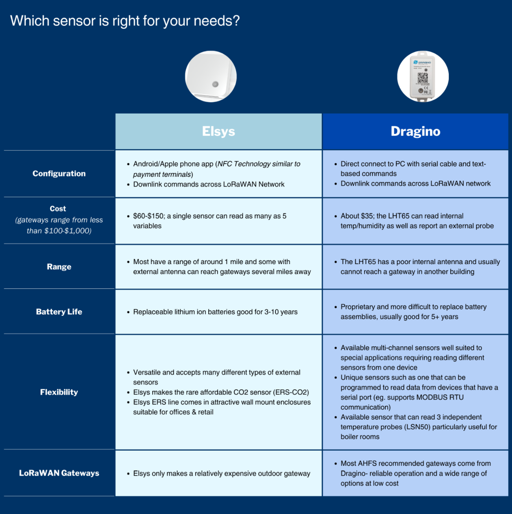
The primary LoRaWAN sensor manufacturers, Elsys and Dragino, are covered throughout this section and in more detail in the Appendix - Configuring LoRaWAN Sensors and Appendix - Notes on Various Sensor Applications. There are dozens of additional manufacturers that make compatible LoRaWAN sensors, but these two manufacturers cover building monitoring needs well. A comparison of these two brands is below.
LoRaWAN Sensor Comparison
Sensor Types
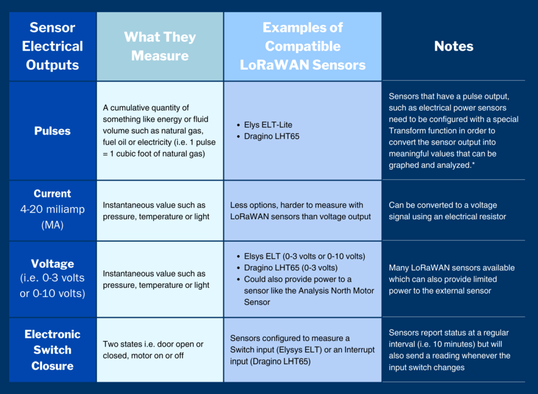
These two sensor platforms are able to read numerous types of sensors and post their data to BMON. In general, sensors have four types of electrical outputs, detailed below.
Types of Electrical Outputs Found in
Sensors
(*additional information for configurations with pulse output transformation is
available)
Temperature
The temperature at various locations in a building is a valuable quantity to measure. From this temperature data, you can learn whether spaces are being heated or cooled evenly and within a range needed for occupant comfort and efficiently manage heating and cooling needs over time. Heating system failures can potentially freeze pipes and other valuable contents of a building. BMON alerts can notify maintenance staff of heating failures before damage occurs.
Energy Savings with BMON-Guided Temperature Measurements
Potential Energy Savings of Measuring Building Temperature
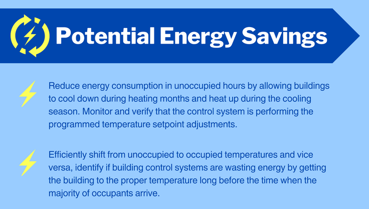
A building’s energy consumption is almost always affected by the outdoor temperature. Heating and cooling energy use relate to heat loss or gain through the building shell, which is proportional to the temperature difference between the inside and outside of the building. When analyzing the energy use data for a building, it is very important to have accurate outside temperature data to make valid comparisons.
Indoor Temperature Collection Methods
Wireless temperature sensors are an excellent and common method to collect indoor temperatures. Depending on your system you may alternatively work with temperature data directly from your building control system or from Ecobee thermostats.
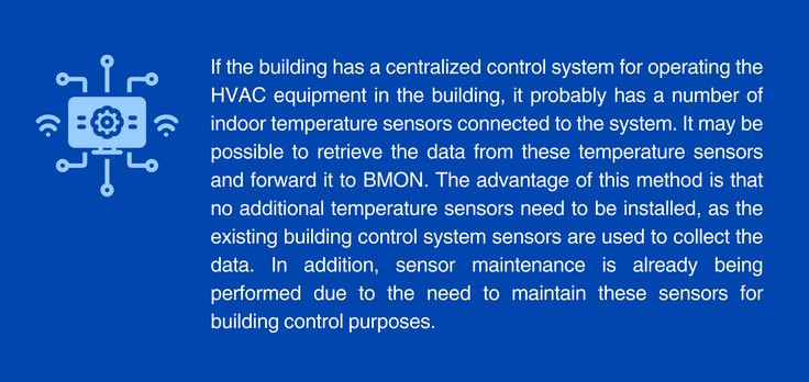
Retrieval from the Building Control System
Collecting Indoor Temperature Data Using an Existing Building Control
System
To determine whether this is a viable technique for temperature collection within your building, contact Tyler Boyes at AHFC.
Retrieval from Ecobee Thermostats
Ecobee Thermostat
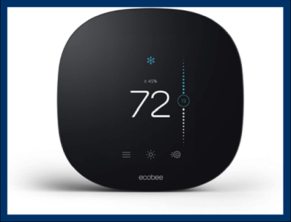
BMON knows how to retrieve data from the Ecobee line of smart, Internet-connected thermostats. If your building utilizes this brand of thermostat, the Ecobee platform can be configured to forward temperature, humidity, temperature setpoint and heating system runtime data to the BMON platform.
Gathering Ecobee Data
Details on configuring BMON to gather Ecobee data are available online. This requires using the “System Administrator” portion of BMON, a topic that is addressed in this section of the manual.
Battery-powered wireless temperature sensors are easy to install, low
cost, and have reasonable battery life (over two years, and generally
last more than four years).
Indoor Wireless Temperature Sensors Tested to Work with BMON
Examples of Elsys and Dragino LoRaWAN Indoor Temperature Sensors
Elsys ERS LoRaWAN Sensor: All of the Elsys ERS sensors provide a temperature reading, ranging from the full-featured ERS CO2 sensor down to the ERS Lite sensor  |
Dragino LHT65 Temperature/Humidity LoRaWAN Sensor 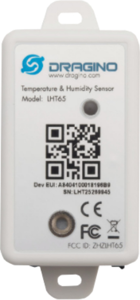 |
The two LoRaWAN sensors listed above also measure humidity of the indoor space. Although humidity is less important than temperature, it does provide information about the comfort of the space. Thirty to 50% is considered a comfortable range of indoor humidity; higher levels may indicate poor ventilation and can potentially drive damaging levels of water vapor into the shell of the building.
Outdoor Temperature Collection Methods
There are a number of good methods for collecting outdoor temperature data for a building. The National Weather Service has numerous weather stations in Alaska, and the Weather Service makes this data available on the Internet for free. BMON has the capability to retrieve this data directly from the Internet and this is the preferred source of outdoor temperature data, since a sensor does not need to be purchased or maintained, and the quality of the data is generally good. For additional information on the use of Mesonet API and wireless temperature sensors, click below.
National Weather Service (NWS): Information is available online on how to integrate NWS data into your BMON system using the System Administrator functions of BMON. You can also acquire wind speed data from the NWS using this method.
Details on the System Administrator functions of BMON are in this section of the manual.
Mesonet API Weather Data
Synoptic Developers provides a service called the Mesonet API, which provides weather data from a wide variety of weather station networks, including the National Weather Service. Limited use of the Mesonet API is free, but extensive use requires enrolling in a paid subscription. Only use this service if you don’t have a nearby NWS station that can be acquired for free from NWS. How to acquire data from the Mesonet API is available online.
Wireless Temperature Sensor Weather Data
If an existing weather station is not available, using a wireless
temperature sensor placed outdoors is a reasonable method for collecting
outdoor temperature data. Here are some choices for wireless temperature
sensors:
Wireless Outdoor Temperature Sensor Options
Elsys ELT-Lite LoRaWAN Sensor: This weatherproof unit can accept many types of sensors, including a temperature sensor. Elsys sells an external temperature probe that can be used to sense outdoor temperature, or a bare DS18B20 temperature sensor can be attached inside the ELT-Lite unit.  |
Dragino LHT65 Temperature/Humidity LoRaWAN Sensor: This sensor is reasonably weatherproof, although some overhead protection would be desirable.  |
When installing an outdoor temperature sensor, the most common mistake is to install it where sunshine can affect the reading. In Alaska, the summer sun wraps around to the north side of buildings, so simply installing a sensor on the north side is not enough to avoid distorted readings at some times of the day. If you cannot find a completely-shaded spot, consider using a solar radiation shield such as this one in addition to placing the sensor in the most shaded location. Also, mount the sensor at least 3 feet away from building walls, as the sun on those walls and heat loss from the building can distort the temperature readings.
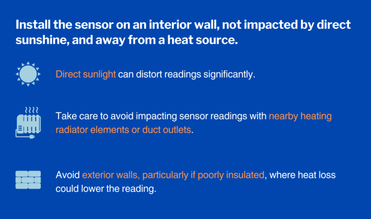
Installing Temperature Sensors
If you are installing your own temperature sensor, as opposed to gathering data from the building control system sensors or from Ecobee thermostats, you should adhere to guidelines similar to installing a thermostat:
Installation Guidelines for Temperature Sensors
Light Levels
Measuring light levels in a building is primarily important for determining when lights are on and when they are off. Despite substantial improvements in efficiency, lighting is still one of the largest electricity uses in commercial buildings.
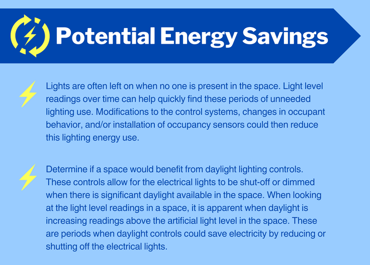
Energy Savings with BMON-Guided Light Level Measurements
Potential Energy Savings of Measuring Light Levels
Light Level Sensors
Wireless battery-powered light level sensors are the best method for measuring light in various building spaces. The two types of wireless light sensors on the market are ‘analog’ and ‘digital’; ‘digital’ sensors are very limited and not recommended. For recommended sensors, click below.
Analog Light Level Sensors
“Analog” sensors measure the amount of light, or light levels, usually in units of lux. Typical office lighting levels are 500 lux or more. This is the preferred type of sensor.
Digital Light Level Sensors
Some manufacturers sell a “digital” light sensor that only reports whether lights are on or off. While determining the on/off status of a light is the primary purpose of reading light levels, this type of sensor is difficult to calibrate correctly so that it accurately knows when lights are on. Daylight can trigger the sensor to report that lights are on even though they are not. This sensor does not provide information on how much daylight a space is getting. For these reasons, “digital” sensors are not recommended.
Here are some recommended wireless light level sensors:
Recommended Wireless Light Level Sensors
Elsys ERS LoRaWAN Sensor: for the ERS Lite and the ERS CO2 Lite come with a light sensor. |
Dragino LHT65-E5 Temperature/Humidity/Light LoRaWAN Sensor: One version of the LHT65 sensor comes with an external light level sensor, which plugs into the main sensor unit via a 20" cable (shown here).  |
Installing Light Level Sensors
Guidelines for installing light sensors depend on the purpose for which you are monitoring light levels. To determine whether lights are being left on at times when they shouldn’t be, install the sensor so that it is nearby and has a good view of a light fixture. Preferably, install it so that daylight from nearby windows does not affect the sensor much. High up on a wall is often a good location. For details on installation of daylight controls, click below.
How Do I Know if I Should Use Daylight Controls?
To determine whether daylight controls could be useful, install the sensor in a location representative of a work surface in the space, such as on a desk. At this location, both artificial light and daylight will be measured in roughly the proportion they contribute to useful lighting. The influence of daylight will make it somewhat harder to determine when artificial lights are on, but it still will be possible.
Indoor Carbon Dioxide (CO2) Levels
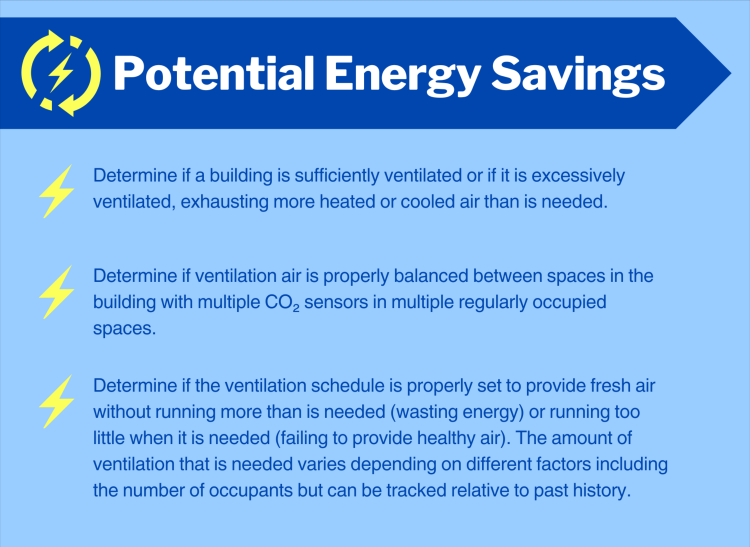
CO2 indicates whether the ventilation system for a building or space is supplying adequate outside air for the health and wellbeing of the occupants. Ventilation helps dilute contaminants in indoor air and replaces oxygen that is removed by breathing. Ventilation can use a lot of energy both in operating the fans that move air through a building, and through the heated air that is exhausted to the outside. So while ventilation is important, it can drive up both the electric usage and the heating fuel usage of a facility if it is not measured.
Energy Savings with BMON-Guided CO2 Measurements
Potential Energy Savings of Measuring Indoor CO2
Levels
Methods of Collecting CO2 data
CO2 can be measured either from a building automation system or with wireless sensors. Use of wireless sensors is described in detail below.
Measuring CO2 from a Building Automation System
CO2 can be measured from a building automation system if one is available. This will usually be a measurement of CO2 in the return air plenum of a building HVAC system so the measurement represents a mix of the air throughout the building. Some modern automation systems have CO2 sensors in spaces, which allows you to see how ventilation air is distributed through a building and/or whether the ventilation airflow is keeping up with occupancy in specific spaces. Accessing CO2 measurements from a control system can be done using this process. A potential downside of gathering CO2 measurements from a Building Automation Systems (BAS) is that the sensors may drift out of calibration. Also, if only one measurement exists, the correct reading will be hard to determine.
Calibrating Your CO2 Sensor
CO2 sensors require calibration, following the appropriate set-up procedure is important. Refer to page 13, Section 7.4 of the Elsys Operating Manual.
Wireless sensors are currently limited to a few manufacturers, but the
Elsys ERS CO2 sensor has been shown to work reliably.
Elsys Sensor Calibration
The Elsys sensor, when set up properly, auto-calibrates every 8 days so the measurements should be accurate for years and not suffer from the drift that others can experience.

Both the ERS CO2 Lite and ERS CO2 come with a CO2 sensor.
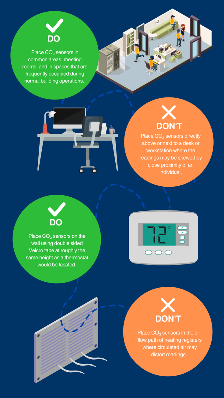
Installing CO2 Sensors
CO2 levels will vary dramatically based on how a space is used and how much ventilation air is supplied to that space. Sensor placement will depend on where you are most concerned about having a lack of fresh air in an occupied indoor space. CO2 is measured in parts per million (ppm). This means small changes in the amount of CO2 in a sample of air can have large impacts on the ppm of CO2 recorded.
What to Consider When Installing CO2 Sensors
Boiler and Domestic Hot Water Temperature
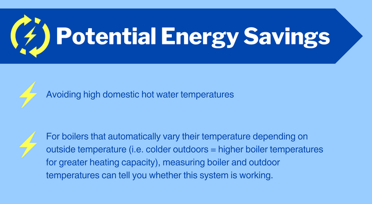
Collecting the temperature of boiler supply and domestic hot water (DHW) supply is relatively easy to do and provides useful information to save energy and detect equipment failures. Significant decreases in either of those temperatures that last for more than a half hour or so probably indicate a failure in the system. BMON alerts can be set up to detect those failures. Also, large decreases in DHW temperature that occur during periods of heavy usage possibly indicate that the system is sized too small.
Energy Savings with BMON-Guided Water Temperature Measurements
Potential Energy Savings of Measuring Boiler and Domestic Hot Water
Temperatures
Methods for Collecting Boiler and DHW Temperatures
Wireless temperature sensors are an effective and always-available method of measuring boiler and domestic hot water temperatures. Click below for alternative methods of collecting these temperatures.
Collecting Water Temperature Data from your Building Control System
Boiler and DHW temperatures can sometimes be collected directly from the building control system, through this process or other ways of communicating with the control system. If heating equipment has a MODBUS interface, a small computer such as a Raspberry Pi can be programmed to retrieve the readings and report them to BMON.
The wireless sensor used for this purpose must have an external
temperature probe. Here are three possibilities:
Wireless Temperature Sensor Options With External Temperature Probes
This weatherproof unit can accept many types of sensors, including a temperature sensor probe. |
Dragino LHT65 Temperature/Humidity LoRaWAN Sensor
The standard configuration of the LHT65 wireless sensor includes an external temperature probe, as shown in the picture above. |
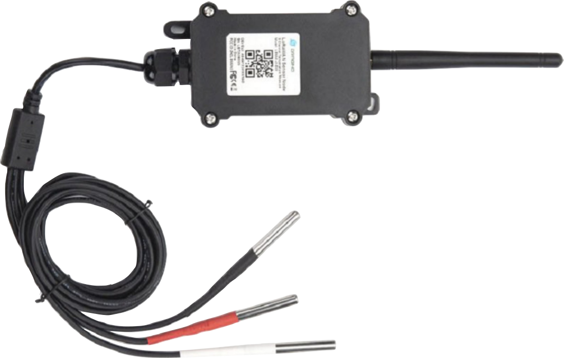
Dragino LSN50v2-D23 Triple Temperature Sensor
This weatherproof unit includes three temperature probes, with about 3 feet of cable on each. Very economically priced (~$60). |
|
Installing Boiler and Domestic Hot Water Sensors
When installing a temperature probe on a pipe, it is important to make good thermal contact for higher accuracy (within 5 degrees Fahrenheit). Thermal heat sink paste, such as this Super Lube product, works well. The image below shows a well done installation of a temperature probe on a pipe:
A Temperature Probe Correctly Installed on a Pipe (heat sink compound promotes good thermal contact and accurate temperature readings)
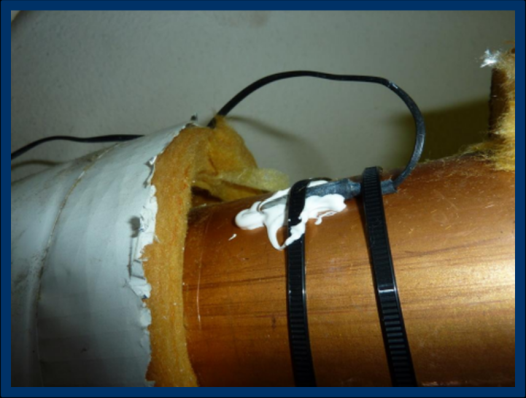
After attaching the probe as shown above, make sure to reinstall the pipe insulation on top of the probe. Make sure to route wires to avoid pulling or snagging when a technician services the boiler or hot water system.
Building Electric Power
Electricity is always a substantial source of energy usage for a building and should be monitored if at all possible. Electricity usage data can be used to find energy saving opportunities in a number of different ways. For more detail, click below.
Energy Savings with BMON-Guided Electricity Use Measurements
Potential Energy Savings of Measuring Electricity
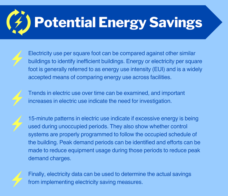
Methods for Collecting Building Electric Data
The easiest way to collect 15-minute electricity use data is to acquire it directly from the electric utility, if that is possible. Many electric utilities are using “smart meters”, which have the ability to collect and transmit 15-minute data back to the utility. To view two alternative methods of collecting electrical use data, click below.
Accessing Building Electric Data from Utilities
Not all utilities utilize this feature or make it available to consumers. But, some do and have made the data available to BMON without charge. These include:
We are currently working with other Alaska electric utilities to capture this type of data, including Alaska Village Electric Cooperative. Hopefully, this data will be available soon. If this option is not available from your utility, please contact Tyler Boyes for assistance with this task.
For other options on how to acquire this data, click below.
Electrical Utility Installs KYZ Pulse Output Unit
Another option is to have your electric utility install a KYZ pulse output unit on your electric meter. That unit will output electrical pulses proportional to how much electricity is being used. A wireless pulse counter, such as the Elsys ELT-Lite or the Dragino LHT65 (previously pictured) can be used to count the pulses and transmit them to BMON.
Electrician Installed Electrical Power Transducer
If the above options are not available, another option is to hire an electrician to install an electrical power transducer on the main power service entering the building. This type of sensor is available from companies such as:
-
Continental Control Systems, the Watt-Node product line.
These sensors generally can output electrical pulses, which can be counted by the Elsys ELT-Lite or Dragino LHT65 sensors, shown above under outdoor temperature collection methods.
Installing Electrical Sensors
If you are not able to collect electrical data from your utility and must use sensors, you will be using pulse output data.
The video below shows how to wire a sensor with a pulse output to an Elsys ELT-Lite LoRaWAN sensor. While the video focuses on a pulse output sensor, its main focus is to give general hints on wiring external sensors to Elsys ELT sensors.
VIDEO: Wiring an External Sensor to Elsys ELT LoRaWAN Sensor
A later section of the manual, Adding a Sensor and Assigning it to a Building, shows how to add and configure sensors in BMON. For more detail on how the data from these sensors must be configured to be useful, click below.
Configuring Pulse Outputs
Sensors that have a pulse output, such as electrical power sensors, need to be configured with a special transform function in order to convert the sensor output into meaningful values that can be graphed and analyzed. How to set up this special configuration is available online.
Building Fuel Use Data
Heating fuel is a major source of energy use in most every Alaska building. Therefore, closely monitoring fuel use is very important for identifying and measuring energy savings opportunities. The benefits of measuring fuel are very similar to the benefits of measuring electricity use, described in this section: Potential Energy Savings of Measuring Electricity. For details on the benefits of measuring fuel, click below.
Energy Savings with BMON-Guided Fuel Use Measurements
Potential Energy Savings in Measuring Fuel Use
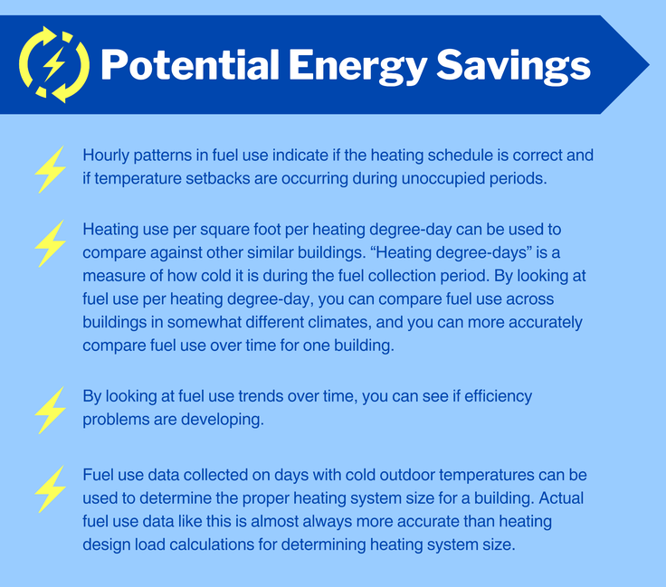
Methods for Collecting Building Fuel Use Data
The method for measuring fuel use will depend on the fuel type. Here we focus on natural gas and fuel oil and also offer a data collection method for buildings using a district heat system (i.e., waste electrical generator heat or a central oil or biomass burner) .
Natural Gas
A couple of different methods are available to measure natural gas use with good time resolution (1 hour or better). For details on these methods, click below.
Meter Transmitter Reading
Most gas meters have a transmitter that sends out the reading on the meter every 30 seconds or so; these transmissions are received by utility meter-reading personnel who typically drive by on a monthly basis. But, these transmissions can also be received by a small computer connected to a “software-defined radio.” The AHFC Mini-Monitor project uses an inexpensive Raspberry Pi computer coupled with a RTL-SDR receiver such as this one to perform this task; the required hardware costs about $120. This set-up can send the received readings to BMON.
Pulse Output Unit
In situations where the gas meter does not have a compatible transmitter or is too far away to be received, the natural gas utility can usually install a pulse-output unit on the natural gas meter. Then, a LoRaWAN wireless pulse counter can be used to read and transmit those pulse counts to BMON.
Natural Gas Meter With a Monnit Wireless Pulse Counter (also shown is a flexible conduit leading to a wireless pulse counter that records and transmits the reading to BMON)
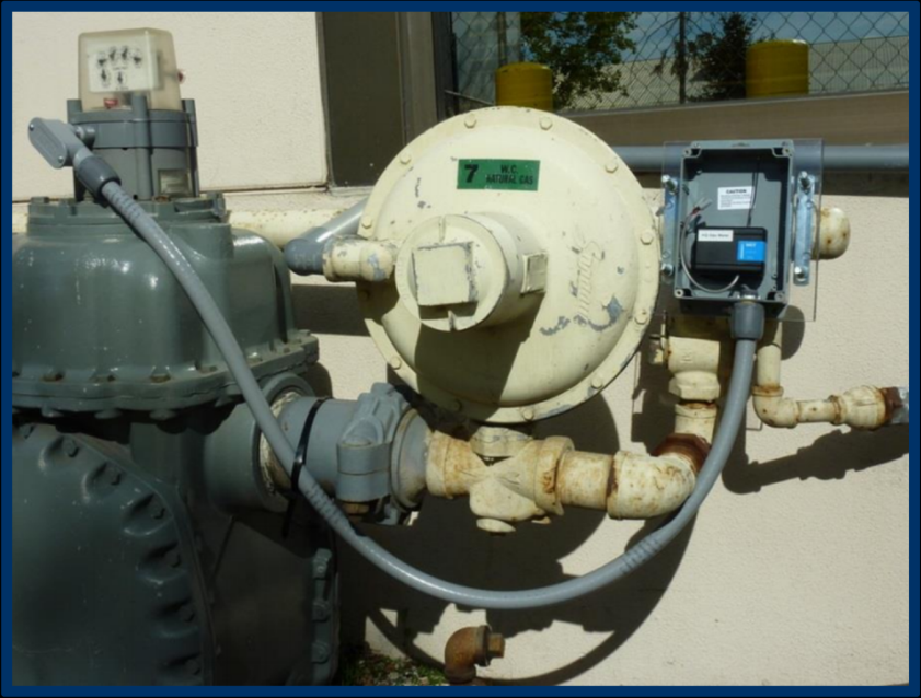
A Monnit wireless pulse counter is shown above. Below is a typical LoRaWAN pulse counter, with a weatherproof enclosure, that can also perform this task:
Typical LoRaWAN Pulse Counter, Elsys ELT-Lite LoRaWAN
Sensor
This weatherproof unit can be configured as a Pulse Counter to read pulses from any meter (electric, fuel, water, BTU) or device equipped with a pulse-output unit.
Fuel Oil
The type of system for measuring fuel oil use depends heavily on the type of heating systems used in the building. Flow meter and tank level methods will work with any system, however local weather conditions such as ice fog can cause problems with the measurements from tank level sensors. Alternative monitoring methods are available for systems with a constant rate of firing and for Toyostoves.
Flow Meter and Tank Level Methods for Measuring Fuel Usage
Flow Meter in the Fuel Line
A fuel flow meter installed in the fuel line is a possibility, although some meters do not measure accurately at the low flows that occur with a Toyostove. Another disadvantage of a flow meter is that the meter introduces another point in the fuel line that can become clogged. Fuel flow meters can be purchased with a pulse output option and then connected to a wireless pulse counter, such as the Elsys ELT-Lite or the Dragino LTH65.
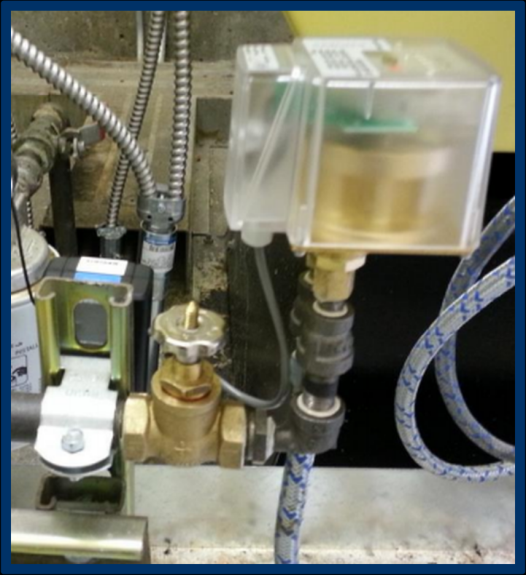
An Elster 4p Fuel Flow Meter Installation (the flow meter is the translucent enclosure in the upper right hand corner of the picture)
Fuel Level in the Tank
Another approach to measuring the fuel use from a tank is to sense the level of fuel in the tank and determine the amount of fuel used from the change in the oil level in the tank. Ultrasonic distance measuring devices or pressure measurement devices can be used to determine tank level. These devices can be battery-powered and transmit their readings via a LoRaWAN sensor. A current project at Alaska Housing Finance Corporation is underway to determine the viability of these approaches.
Fixed Firing Rate Systems
Some fuel oil heating systems utilize a combustion burner that runs at a constant rate of firing / fuel use. For these systems, if you know the firing rate of the burner, you can measure how long the burner is on in order to then determine how much fuel was used.
Firing Rate
If you can determine the size of the fuel oil nozzle used in the burner (e.g., 1.10 gallon per hour, GPH), you have a reasonably accurate estimate of the fuel consumption rate of the heating appliance when it is on. You can refine your estimate of fuel rate by also measuring the oil pressure supplied to the nozzle. The rated flow rate is achieved when the oil pressure at the nozzle is 100 PSI. If the pressure is different than 100 PSI, the flow will be different and can be determined from a chart like this one.
While all of these sensors are handy tools, they will never compare to empirical, hands-on testing. Be sure to verify your readings by dipping the tank and cross referencing with a tank chart. Once you have an estimate of the fuel consumption rate of the heating system when it is on, you then need to determine how to measure the on and off cycles of the boiler.
Fuel Solenoid Sensing
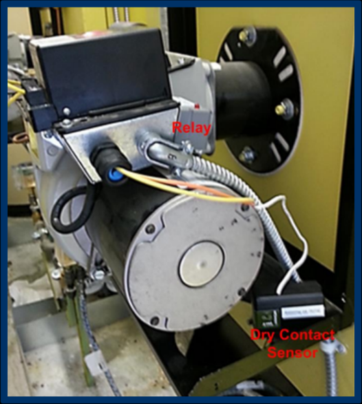
One approach is to connect an electrical relay across the fuel solenoid or the oil burner (sensing the fuel solenoid is more accurate than sensing the burner, since burners often operate for a short period of time both before and after burning fuel). Whenever power is applied to the fuel solenoid (or to the burner), the relay will close; the relay contacts can then be connected to a wireless switch sensor, such as the Elsys ELT-Lite or the Dragino LHT65. These sensors will transmit a reading whenever the burner turns on and off. The image below is one example of a relay connected to an oil burner; a wireless switch (Dry Contact) sensor is shown wired to the relay contacts.
Boiler Burner Fuel Solenoid Showing Placement of a Dry Contact
Sensor
Motor Sensor
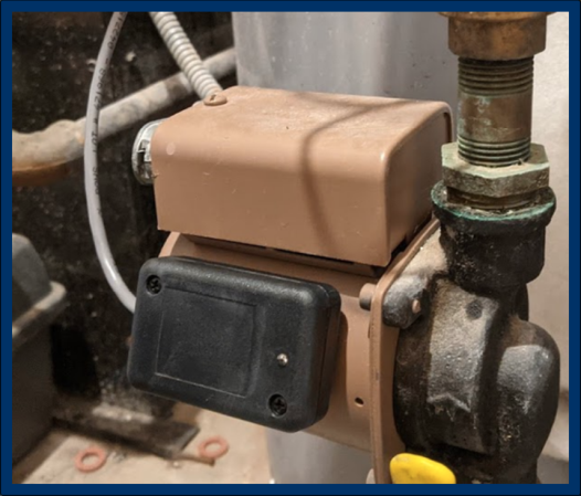
Another approach to monitoring the On/Off cycles of a fuel solenoid or burner is to use a Motor Sensor, such as one made by Analysis North. This device attaches with velcro to a motor or any AC electrical device that energizes a substantial coil of wire. The device senses when the coil is energized and connects to a wireless switch sensor to transmit that reading. The image below shows a motor sensor attached to small circulating pump:
A Motor Sensor Used to Sense Whether a Motor is On or Off
Toyostove Fuel Measurement Device
Toyostove Fuel Measurement Device
A Toyostove heating system has multiple different fuel consumption rates (Low, Medium, High), so simply measuring when it is running will not allow you to make an accurate estimate of fuel consumption. The Alaska Center for Energy and Power has developed a technique for measuring Toyostove fuel consumption by measuring the fuel pump on the Toyostove heater. Contact them to learn more about their PuMA Fuel Meter.
District Heat Systems (i.e, biomass, oil, or electric generator waste
heat)
Some buildings are heated by a District Heat System, perhaps delivering waste heat recovered from an electrical generator or delivering heat produced by a central oil or biomass boiler. You can install a BTU meter on the heat delivery system to the building to measure the heat load of the building. For details on additional methods, click below.
Additional Methods of Measuring Heat Load
The ONICON System 10 and System 40 meters can be used if cutting into the hydronic piping is a possibility. Otherwise, an ultrasonic BTU meter should be used to measure heat delivery. Note that none of these methods measures the fuel burned but can give an accurate measurement of the heating demand of an individual building. LoRaWAN pulse counters or RS485 sensors can be used to report this heat load to BMON.
Typical Sensor Wiring Examples
This section will show some typical wiring configurations for the sensors discussed above. There is a more detailed table of wiring and configuration information for Elsys ELT sensors in the Appendix - Notes on Various Sensor Applications.
Click below for more detail on each configuration.
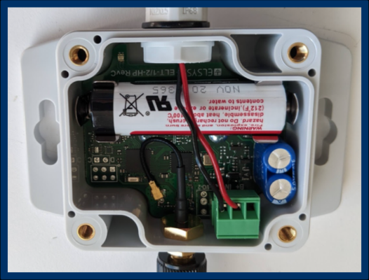
Voltage Output or Switch Closure Sensor Wiring
This image shows how to wire a voltage-output sensor or a switch closure sensor to an Elsys ELT-Lite. The negative or ground lead from the voltage-output sensor goes to the Ground terminal on the ELT-Lite (marked ⏚). The positive or signal lead from the voltage-output sensor goes to the IN terminal on the ELT-Lite. When connecting a switch-closure or pulse-output sensor, the wiring is the same. Some switch and pulse sensors have no positive/negative polarity to their connections, but other sensors do have polarity: positive to IN and negative to ⏚ ground.
Wiring a Voltage-Output Sensor or a Switch Closure Sensor to an Elsys
ELT-Lite Sensor
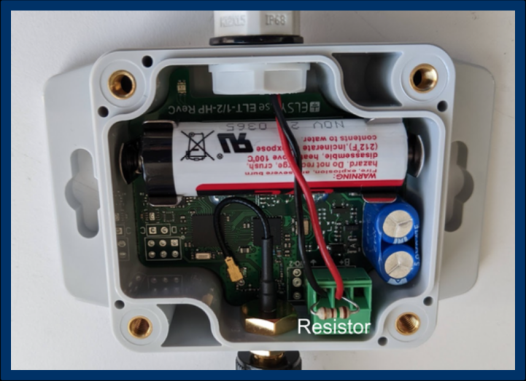
Converting a 4-20 mA Current Output Sensor to Voltage with a Resistor
If you are reading a sensor with a 4-20 mA current output, you can convert the current into voltage by using a resistor, as shown in the image below. The resistor wires across the IN and ⏚ground terminals of the ELT-Lite. An appropriate size resistor is 150 ohms with 1% accuracy. Then the ELT-Lite can be configured to use the 0 - 3 Volt Analog Voltage scale. The following formula will convert the voltage read by the ELT-Lite into the engineering value read by the sensor:
(technical note: for those that know Ohm’s law, the above formula is derived from an effective resistance of 147 Ohms, since the ELT-Lite has an internal resistance of 7,400 Ohms in parallel with the 150 Ohm resistor value).
BMON can do this conversion by entering a formula into the Transform field when setting up a sensor. As an example, assume the sensor is a 10 PSI pressure sensor. The appropriate Transform formula to use in BMON would be:
since the “val” variable holds the voltage read by the sensor.
Correct Wiring of a 4-20mA Output on an ELT-Lite Sensor With
Resistor
Wiring for a Sensor that Needs to Receive Power from an Elys ELT-Lite Battery
This image shows the appropriate wiring for a sensor that needs to receive power from the Elsys ELT-Lite battery. An example of such a sensor is the Analysis North Motor Sensor. The Red lead going to the Motor Sensor needs to be connected to the battery terminal of the ELT-Lite, which is marked B+. The White lead from the motor sensor is the signal output lead, which acts like an electronic switch, and is connected to the IN terminal on the ELT-Lite. Finally, the Black lead from the motor sensor goes to the ground ⏚ terminal on the ELT-Lite. Similar wiring is used for any external sensor that needs to receive power from the ELT-Lite.
Correct Wiring of an External Sensor Powered From the ELT Sensor Battery

For external sensors that need to receive power from the ELT-Lite, configuration of the ELT-Lite is important. In the “Sample Times” section of the ELT-Lite configuration parameters, there is a setting labeled “External startup time.” This setting determines how early power is applied to the external sensor before the sensor is read. The setting is expressed in milliseconds. For some sensors such as pressure sensors, power can be turned off except for a short period of time prior to reading the sensor. “External startup times” as short as 20 milliseconds can work. But some sensors, such as the Analysis North Motor Sensor, require that power be applied continually to the sensor. The “External startup time” settings should be set to 10 million in those cases (10000000), to ensure that power is continually applied to the external sensor.
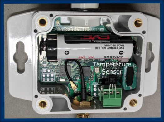
Wiring a Temperature Sensor Inside the ELT-Lite
This image shows a small temperature sensor wired inside the ELT-Lite. Electronically, this is the same sensor that is sold as the Elsys Temperature probe but is less expensive, less obtrusive, and can be used if air temperature needs to be measured. (The “1-wire Temperature Probe” is the correct External Sensor setting on the ELT-Lite.) The model number for the sensor is DS18B20, and sensors are available on Digikey, Amazon or other sources. When wiring the sensor, the flat face of the sensor should be facing up as shown in the photo below.
Internal Temperature Sensor Wired Inside the ELT-Lite Sensor Enclosure
Connecting Wireless Sensors to the Internet with Gateways
All wireless sensors need a gateway that serves as a central receiving device to route sensor readings to the internet. One advantage to LoRaWAN sensors is that the gateway and sensor do not need to be from the same manufacturer or installed on the same account. Gateways are automatically shared across all users of the Things LoRaWAN network. This means that sensors can transmit data through other gateways if they are within range of the sensors.
Gateways for Wireless Sensors
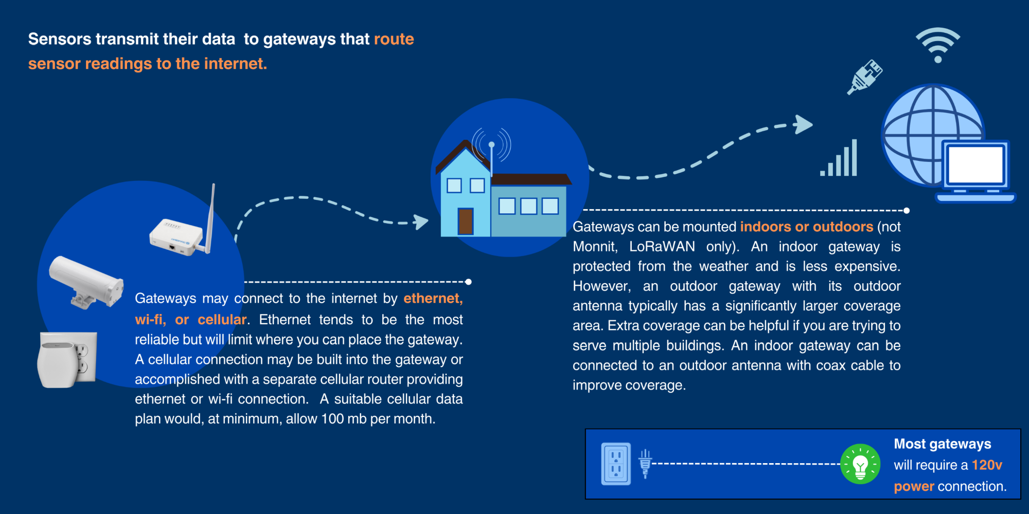
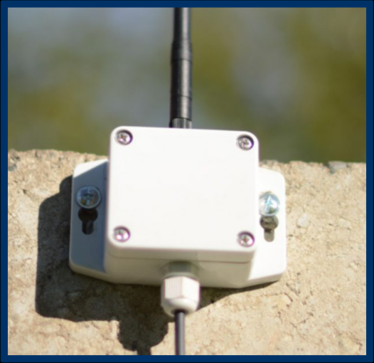
Gateways usually require 120V wall power and may connect to the internet by an ethernet, Wi-Fi, or celluar connection. Ethernet tends to be the most reliable but will limit where you can place the gateway. A cellular connection will need a minimum of 100 MB month of data. Indoor gateways are protected from the weather and less expensive but an outdoor gateway with its outdoor antenna, will have better coverage. Extra coverage can be helpful if you are trying to serve multiple buildings with one gateway. Another solution is to connect an indoor gateway to an outdoor antenna with coax cable as seen in the photo below. This solution also keeps the gateway electronics protected from the elements.
Here are some good choices for LoRaWAN gateways:
Pros and Cons of Select LoRaWAN Gateways
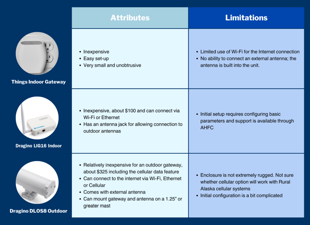
Instructions for Things Indoor Gateway
Dragino Gateway Setup
Setup instructions for the Dragino gateways are found in their User Manuals; some helpful hints are also provided in the Appendix- Configuring Dragino LoRaWAN Gateways. For setup purposes, the gateway will act like a Wi-Fi access point, which you can connect your laptop to, and then browse with your browser to the Setup page for the gateway. When you go to the Wi-Fi setup page, make sure you keep the Wi-Fi access point enabled so you can come back later, if need be, to change settings.
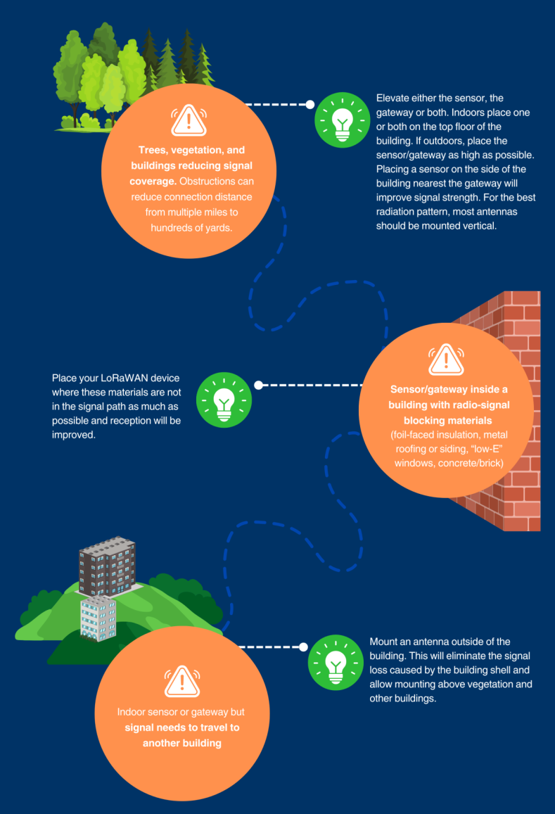
More Notes on LoRaWAN Signal Coverage and Antennas
Gateways and Sensors communicate via radio signals, and both gateways and sensors use antennas to radiate and receive signals. If a sensor is having a difficult time reaching a gateway, you can either move the sensor or improve the antenna of the sensor. Another option is to improve the location or antenna of the gateway (or both).
Solutions for Potential Sensor Connection Issues
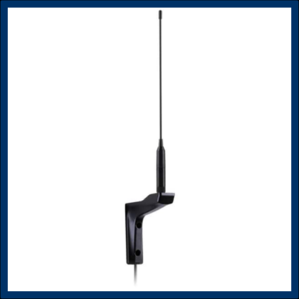
This image shows a simple external antenna that can be used with a sensor or gateway to improve signal strength between buildings.
Simple External Antenna That Can Be Mounted on a Wall Or Roof Fascia
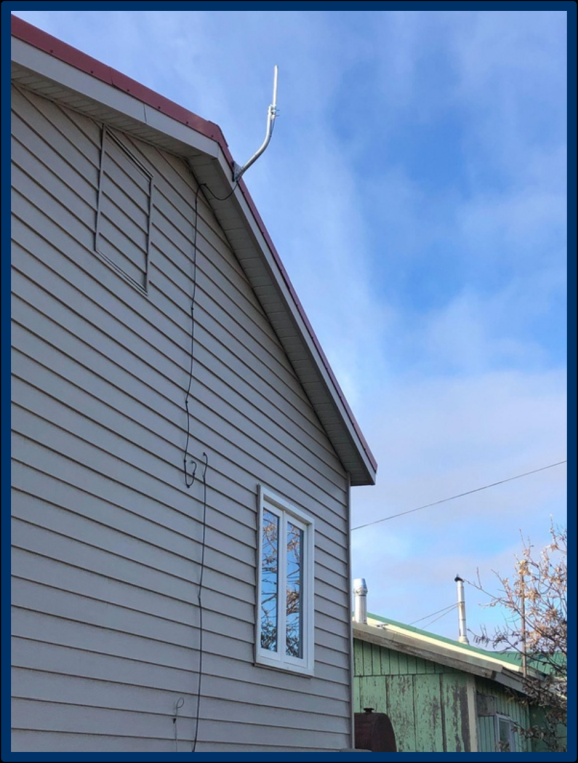
This photo shows a more capable antenna installation with the antenna mounted above the roof of the building. This antenna is being used with a gateway to cover a large portion of downtown Nome, Alaska. Note the drip loops on the coaxial cable (to prevent water leakage into the building) and the placement of the antenna above the peak of the roof.
A Properly Installed Exterior Antenna for a LoRaWAN Gateway
Sourcing External Antennas and Mounts
-
Antennas for LoRaWAN in the US must be tuned for the 900 - 930 MHz frequency band. They are generally marked “915 MHz” or “900 MHz”.
-
The antennas shown so far are: Taoglas WM.95.A.305111, available Here. Dragino Outdoor 915 MHz Antenna, available Here. Similar models available on Amazon, such as this one.
-
A J-pipe antenna mount shown in the picture above is available here.
Antenna Connections Notes and Sourcing
-
Signal loss occurs on the coax cable between the Antenna and the LoRaWAN gateway or sensor. A good choice for low-loss coax is Times Microwave LMR-240 for distances up to 60 feet. For distances less than 30 feet, Times Microwave LMR-200 is acceptable.
-
The end of the coax that connects to the gateway or sensor generally needs to have an SMA Male connector. The coax connector on the antenna end needs to mate with the connector on your antenna. You generally can buy a coax customized with the connectors you need and the length you want. Online, WiFi Expert can provide custom coax cables.
-
These clips can secure the coax to the building.
On a final note, often installing multiple inexpensive, indoor gateways
in different buildings can be as effective as installing one outdoor
gateway or a gateway with a high external antenna. Multiple gateways
also provide redundancy if a gateway or the Internet serving the
gateways fails.