Appendix: Notes on Various Sensor Applications
This Appendix gives wiring diagrams and configuration settings relevant to a number of different Sensor Applications, such as sensing the runtime of a motor and measuring the fill level of fuel tank.
Notes About External Sensors Connected to the Elsys ELT-Lite or ELT-2
In this section we give some details about how to connect and configure a variety of external sensors to the Elsys ELT-Lite or ELT-2 sensor. Consult the Elsys ELT User Manuals (ELT-Lite, ELT-2) for more details.
Elsys External Sensor Wiring and Configuration
| Sensor Type | Elsys Configuration & Wiring | BMON Configuration |
|---|---|---|
| Temperature Sensor This must be a DS18B20-type temperature sensor such as the one sold by Elsys or these on Amazon. It can also be a bare DS18B20 mounted directly to the terminal block in the Elsys. Note that the ELT-2 has a built-in temperature and humidity sensor, in addition to allowing for an external sensor. |
“External sensor" setting on the Elsys should be “1-wire Temperature probe". Wiring of the external probe is:
Sensor Wire : Elsys Terminal
Red : B+ Yellow/White : IN Black : Gnd ⏚ For the bare DS18B20:  |
The external temperature sensor shows up as a “xxx_extTemperature" (°F units) Sensor ID; the internal sensor in the ELT-2 is “xxx_temperature" and “xxx_humidity" (%RH units) for the relative humidity measurement. |
| Pulse Output Sensor Sensors like electric power transducers, fuel flow meters, water meters. |
The two wires from the pulse output wire to the IN and Gnd ⏚ terminals on the Elsys. Some pulse output sensors are pure dry switch closures (e.g. reed switches in water meters and fuel flow meters), so there is no polarity to the wiring. Some pulse output contacts are done electronically and have a + and a - terminal. + goes to IN on the Elsys, and - goes to Gnd ⏚. |
The pulse count shows up in BMON as “xxx_pulse". It will be a cumulative pulse count and is usually converted into a rate-of-use value like gallons/minute or kW, using the special “rate" variable in the BMON Transform. See this section of the BMON documentation. |
| Analysis North Motor Sensor This sensor attaches to a motor or other electric device emitting an AC electric field, and it senses when the device turns On and Off. 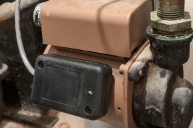 |
Wiring to the Elsys is:
Sensor Wire : Elsys Terminal Red : B+ White : IN Black : Gnd ⏚ The “External Sensor" setting should be “Switch, dual edge trig", which causes the Elsys to send a reading when the sensed motor turns On and when it turns Off. The other critical setting in the “Sample times" section of the configuration is the “External startup time", which should be set to 10 million (10000000, a 1 with seven zeroes and no commas). This setting ensures that battery power will be continuously delivered to the Motor Sensor from the Elsys ELT. |
Readings appear in BMON with a Sensor ID of “xxx_digital". A good unit selection is “1=On 0=Off" since the reading value is a 1 when the motor is On and a 0 when it is Off. |
| Switch Closure You may have a Relay wired across a device to sense when the device turns On and Off. Or, you may have a door sensor that closes a switch when the door shuts. |
For a dry switch closure, there is no polarity and wiring at the Elsys is across the IN and Gnd ⏚ terminals. The “External Sensor" setting should be “Switch, dual edge trig" if you want to receive a reading for both a closing and an opening of the switch. If you just want a reading when the switch closes, select “Switch (normally open)". |
Readings in BMON are the same as with the Motor Sensor: “xxx_digital" Sensor ID, and a value of 1 when switch is closed and 0 when it is opened. |
| Sensor with 0 - 10 VDC Output Pressure sensors and other types of sensors can be obtained with a 0 - 10 VDC output signal. |
Here we are assuming that the external sensor has its own power supply. To read the output with the Elsys, you need two wires from the sensor, wired as follows:
Sensor Terminal : Elsys Terminal Signal Output (0 - 10 VDC) : IN Ground : Gnd ⏚ The “External Sensor" setting should be set to “Analog 0-10V". |
Readings in BMON arrive with a Sensor ID of “xxx_analog", measured in Volts. A BMON Transform is required to convert this to engineering units. For example, if a pressure can read a maximum of 25 PSI, which corresponds to 10 V output, the Transform formula to produce readings in PSI would be: 25.0 * val / 10.0 |
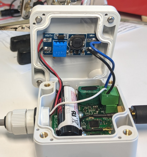
| Sensor with 0 - 10 VDC Output, powered by the Elsys With the addition of a Voltage Converter board, it is possible to have the Elsys ELT supply power to an external sensor that needs a relatively high power supply voltage. Sensors with a 0 - 10 VDC output generally need a power supply voltage of 14 Volts or more. The Elsys battery itself can only supply about 3.6 Volts. |
Here is a suitable voltage converter board. The picture below shows it mounted in the Elsys ELT-Lite enclosure:
The screw-adjustable potentiometer on the board must be set to provide the proper voltage to the external sensor, usually from 14 - 24 VDC. Wiring is as follows: Sensor + Power Input → VOUT+ on Converter Sensor Gnd → VOUT- on Converter Sensor 0 - 10V Output → Elsys IN VIN+ on Converter → Elsys B+ VIN- on Converter → Elsys Gnd ⏚ For the Elsys configuration, “External Sensor" is set to “Analog 0-10V". The “External startup time" setting determines how early power is applied to the external sensor before it is read by the Elsys. Some sensors need as little as 20 milliseconds to stabilize. Others can require 750 milliseconds or more. Experimentation or an oscilloscope test can determine this value. Longer times are the safe approach but reduce battery life. |
Same as the prior row, “xxx_analog" is Sensor ID, and a suitable BMON Transform must be entered to convert to engineering units. |
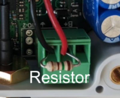
| Sensor with 4 - 20 mA Current Output Some sensors have a current output varying from 4 to 20 milliamperes (mA). The Elsys ELT cannot read current directly, but a resistor can be used to convert the current output into a voltage output, which can be read by the Elsys. |
The proper resistor value is 150 Ohms, 1% accuracy. Here is a wiring picture:
The red and black wires go to the 4 - 20 mA sensor; the negative return wire from the sensor is cut and the red and black leads are wired as follows:
The “External Sensor" setting should be set to “Analog 0-3V". |
The Sensor ID will be “xxx_analog". A BMON Transform is needed to convert the voltage into engineering units. The Transform should be:
<full-scale value> *(val - 0.588) / 2.352 So, for a pressure sensor with a max value of 25 PSI, the Transform would be:
25.0 * (val - 0.588) / 2.352 (this accounts for the 7,400 Ohm internal resistance of the Elsys ELT). |
| Maxbotix Distance Sensor Can be used to measure depth of fuel in a fuel or water tank. |
Can be used with an ELT-2. Set the "External Sensor" setting to "Maxbotix". Red wire Maxbotix → Elsys B+ Clip the shield and all other colored wires. |
|
|
Fuel Tank Level Sensor 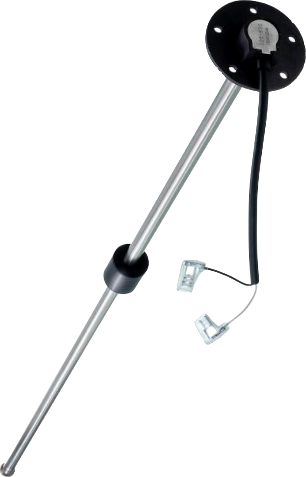 |
ELT wiring involves a 150 Ohm 1% accuracy resistor connected from the B+ terminal to the
IN terminal. The fuel sensor wires connect to the IN and Gnd ⏚ terminals as
shown here with an ELT-Lite:
 Important settings for the ELT sensor are: |
Most fuel float sensors, including the one linked to in the left column, have a varying resistance output from 33 Ohms (full) to 240 Ohms (empty). With this sensor, the following BMON Transform will produce a value of 0 for Empty and 100 for Full: (1-(150*val/(3.5-val)-33)/207)*100 This value will be affected by battery voltage (assumed to be 3.5 Volts in the above Transform) and temperature. If higher accuracy is needed, A more complicated BMON setup is possible. Contact the BMON development team for more information. |

Miscellaneous Sensor Wiring and Configuration
The table below gives details on use and configuration of some selected LoRaWAN sensors, not addressed in the prior Elsys table.
Use and Configuration of Selected LoRaWAN Sensors
| Sensor | Configuration & Wiring | BMON Configuration |
|---|---|---|
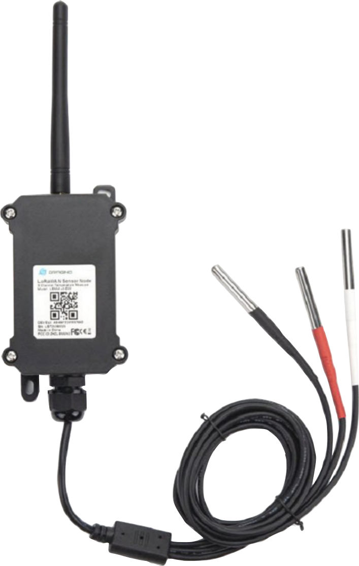
| Dragino LSN50v2-D23 This sensor comes with three external temperature probes. An example use is to measure boiler supply, boiler return, and domestic hot water temperatures. |
Dragino sensors generally need to be configured by AHFC, as configuration is done with a serial-cable connection to a PC. For this particular sensor, no special wiring is required, as it comes pre-wired with the three sensors, color-coded with black, red, and white heat shrink tubing:
|
The temperature sensors show up as “xxx_extTemperature1", “xxx_extTemperature2", and “xxx_extTemperature3" (°F units) Sensor ID, where “xxx" is the Device ID (EUI). The color coding on the probes is as follows: White: temperature 1 Red: temperature 2 Black: temperature 3 |